


b12ty
-
Posts
291 -
Joined
-
Last visited
Content Type
Profiles
Forums
Events
Posts posted by b12ty
-
-
Ack, that sucks, who would have known by looking at it that they were 1/2" different. I didn't need to remove my center stand, BUT... I have the low profile oil drain plug installed. Makes all the difference.
Carry on, good luck.
Ty
-
My 2 cents, ANY oil that is JASO MA certified for wet clutch, with proper viscosity, is fine. Period.
JASO MA2, good enough for me!
Ty
-
Looking good, sound clips soon I hope!More progress...
Started packing the muffler:
Layer 1, fiberglass mat packing material -
Layer 2, stainless steel wool mat packing material -
Layer 3, coarse stainless steel wool (food service scrubbing sponges) -
Obviously, these layers will be repeated on top, under the 'lid' as it gets welded back on. My hope is that the coarse stainless wool will take most of the sound energy out of the exhaust pulses before it gets to the fiberglass, making it both reasonably quiet, and durable. There's lots of room in the muffler, and I'm packing it tightly, except where things are pretty narrow on the right side, so there's not a lot of material there. Hope to get the top welded on later today.
Ty
-
Aha! I figured there had to be some delay or the "on" signal would turn out the knuckleguard light. That's why the video is edited everytime it shows a different mode.I think there is a bit of confusion about the turn signal flash function with these LED conspicuity lights.
The light assemblies have 2 wires, + and ground.
If you desire them to flash with you turn signals, you will need either:
a control box (as illustrated in the instructions but NOT included in my kit)
homebrew control circuit.
The light assemblies do not have the control box built in.
Control of the LED's is more complicated than the front turn signals / running lights as they have 3 wires, + for running, + for turn, and ground. When the turn signals are flashing, the power is applied then removed from the + turn lead by the flasher relay.
A functional spec for the control box or circuit is as follows:
[span] If power on, light the LED
[/span][span] When the turn signal power comes on, leave the LED illuminated until the turn signal turns off.
[span] Once the turn signal goes off, extinguish the LED.
[span] If the power is on, and the thru signal power has not been on for approximately 4 seconds[/span] re-illuminate the LED
This is how the halo lights in a lot of cars operate. Should be able to source the control box somewhere.
[/span]
[/span]
I had a electronic flasher on another bike that would delay like that. Ended up putting in resistors instead to slow down the flash rate. Maybe not directly related to this, but was annoying.
Not sure i'd like it to skip a cycle, when changing lanes for example. But considering it's not the main signal, and in front, maybe no biggie. I may just use mine wired up as signals only. ( would have to cover them with amber tape. )
Ty
-
What you are describing is a circuit that would turn OFF the lights when the bikes signals go on. ( thus being out of synch ) However, in the video the front and rear signals appear to be in synch with the LED lights. That has me baffled as to how that is accomplished. What am I missing?
I've got an electronics background, so it seemed pretty straight forward to me. There are 3 wires going to the stock front turn signals, ground, turn and running (12v constant). You can tap those directly using the 3 wires from the converter. Output from the converter is two wire, ground and constant (12v). Those two wires go to the LED knuckle guards. The converter will light the LEDs until the turn signals are activated at which time it will switch power on/off/on/off. Once the turn signals are extinguished, the power is constant again.Any chance you can explain or show how you wired these to sync with your turn flashers? Even with the instructions I could not figure how to wire them?

[video src=http://www.youtube.com/watch?v=Sgr8fEPDsm8]
Ty
-
Ya, I was thinking of some film like that. But i'd rather have it molded in that color in the first place. Oh well, always something new!
I've got mine wired as running lights/turn signals and they won't pass inspection unless they are amber. I'll simply purchase some transparent self adhesive Amber/Orange vinyl. Might even leave the film on there if I like it better. linkNOOOOO!!!!
I wonder if I can return mine. I wanted to set them up as turn signals anyways..... if they had included the module shown in the instructions.
Ty

So yours came with the turn signal module then?
Ty
-
They just released the amber colored version I see on Ebay- http://www.ebay.com/itm/YAMAHA-FJ-09-MT-09-TRACER-Knuckle-guard-LED-Kit-Orange-color-Sync-module-/321766259501?hash=item4aeac37b2d.
NOOOOO!!!!
I wonder if I can return mine. I wanted to set them up as turn signals anyways..... if they had included the module shown in the instructions.
Ty
-
Some more progress today... got the perforated tube and outlet welded in.
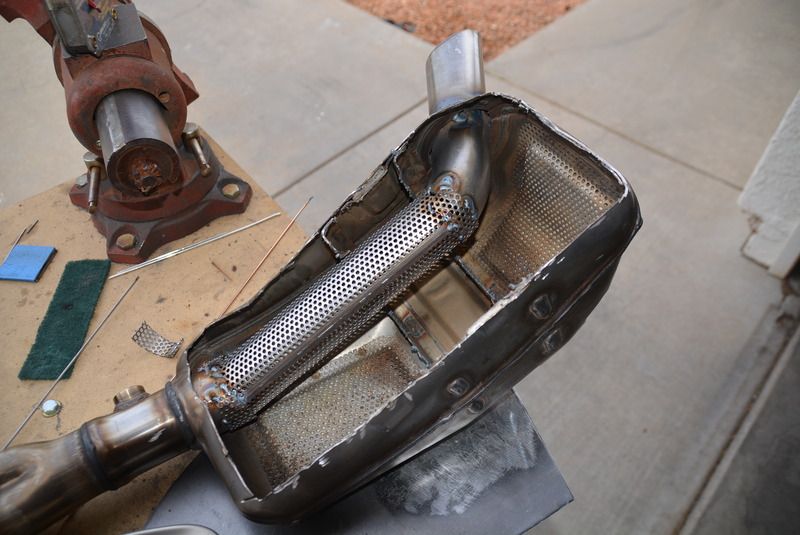
Now I just need to fabricate brackets for the decorative outlet cover, pack it, and weld the top back on. Sorry for the slow progress, but I'm trying to cram this in between the rest of my life...
The important thing is progress, looking good!
Ty
-
My tip is dark also. Ya, I figure I may be giving up a couple of HP on top, but it's worth it to make it sound exactly the way I want.The O2 probe is from innovate. The cross section of it might be 1/2" by 3/4".....the part that gets inserted into the pipe anyway. The fact that it sticks into the muffler a piece may screw the flow up too besides it just reducing the outlet size. As far as fueling, I think the fact that you can order these bikes with dealer installed Akra systems suggests the factory map is a bit over rich at WOT to allow for this. The tip of my exhaust is plenty dark on the inside, she's gettin plenty of fuel.

Ty
-
as long as you don't overdo it and end up clutching your slippersI can feel my own clutch slipping this time of the evening but my Tracer does not have a slipper clutch.

Ty
-
Hey, good to know our fueling is not messed up by doing this mod!
I had my bike back on the dyno as I was curious to see the fueling without a remap. Other times I had not bothered, but I just wanted to check so I know where things are. With my modded exhaust the fueling is steady at 12.9-13.0 across the board from 4-11000. I put this in this thread because I noticed something when making a backup run without the probe stuffed in the outlet. It made 3hp less with the "wand" in the outlet than with it out. I think this confirms the bigger outlet is worth hp....but again, that was never the point of all of this in the beginning. Just passing along results.Well, as Lewis noted in one of his posts, he definitely noted a power increase with stock tip. As do I still, even with stock diameter insert. Front wheel still gets awful light where it didn't stock! Top end? Who knows without a dyno. I'm making my insert removable of course... so I can have it both ways.
I believe the gains are made mostly with the second hole in the cat chamber. ( along with removing the s pipe, of course ) It's designed to have the output of the cat slammed into the rear chamber wall, then have to go sideways and back to get to the rear chamber. As you noted, your dynoed gains came from what you thought was reduced back pressure from the cat chamber. The second hole is right inline with the cat.
Fun stuff!
Ty
Just out of curiosity, how big was the probe you stuck in your outlet? Enough to account for the difference of a 1.5" to 2" tip ya think?
I did go ahead and make a DB killer of sorts. A tapered I.D. reducer bushing that fits inside the 2" tip. I then welded the original tip to that, and secured it inside the 2" pipe with a couple of screws that I threaded into the bushing. Softens the sound at idle, and doesn't sound so "boomy" inside my helmet. I'll have to get a pic of it sometime. Sounds great on the throttle still, and easily removable if I want.
rodan, any plans to dyno your bike after you finish the exhaust?
Ty
-
Get it while they are available....

Ebay Link
Ordered, .. my credit card hates you!
Think i'll paint the screws black.
Ty
-
ULEWZ, Any updates on how this Mazda FS50-21-249 low profile oil plug worked out?
You can see my thread on Mazda plug install here. link
Didn't have any problems, but as noted make sure you don't overtighten. Have yet to change oil again. Another thing it does help is if you ever have to remove the exhaust system. More clearance!
Ty
-
For those of youse who are on the fence about buying either the FJR bag or the FJ bag, you can purchase set of unpainted FJR bags for the price of FJ bag (Painted ones are too damn expensive). Unpainted FJR bags actually have two tone colors. Base of the bag is plain unpainted black plastic just like FJ bags and the lid has matte sheen to it. I think it actually blends in nicely with rest of the bike. I have a red FJ and set of unpainted FJR bags and it looks great! So whether you have a grey or a red fj, you can't go wrong. You just gotta get in line for the lower mounts like I am!
Pics, or a link?
Ty
-
Perforated tube going to run the whole length of the muffler, I assume? Then pack with fiberglass/steel wool? Ya, that does sound like a typical aftermarket pipe. Basically what I have on my other bike, and that sounds perfect.

Looking forward to pics and sound clips.
Ty
-
Well, as Lewis noted in one of his posts, he definitely noted a power increase with stock tip. As do I still, even with stock diameter insert. Front wheel still gets awful light where it didn't stock! Top end? Who knows without a dyno. I'm making my insert removable of course... so I can have it both ways.
I believe the gains are made mostly with the second hole in the cat chamber. ( along with removing the s pipe, of course ) It's designed to have the output of the cat slammed into the rear chamber wall, then have to go sideways and back to get to the rear chamber. As you noted, your dynoed gains came from what you thought was reduced back pressure from the cat chamber. The second hole is right inline with the cat.
Fun stuff!
Ty
-
Looking forward to the results!
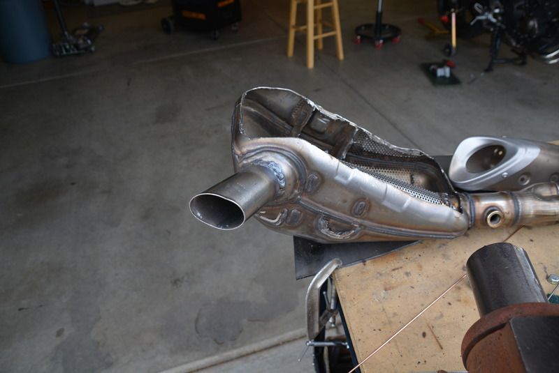
Are you gonna keep the stock exhaust tip, or go bigger? I went with the 2" outlet, but i'm not sure it's needed.
When I did Lewis's muffler, we kept the stock tip, nice sound, and power increase! And not as "boomy" at idle. In fact i'm experimenting with a mild DB killer, basically going back to stock outlet diameter. Not quieter, just softer at idle. Took a ride this morning, and that triple sounds really sweet. Man, I love this mod!
Just removing the S pipe and adding second outlet from the Cat chamber is all that is really needed imo. Just FYI to any who are contemplating doing this mod.
I'm also very curious to see how rodan's approach turns out!
Ty
-
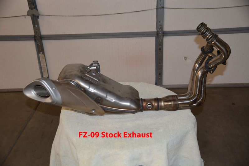
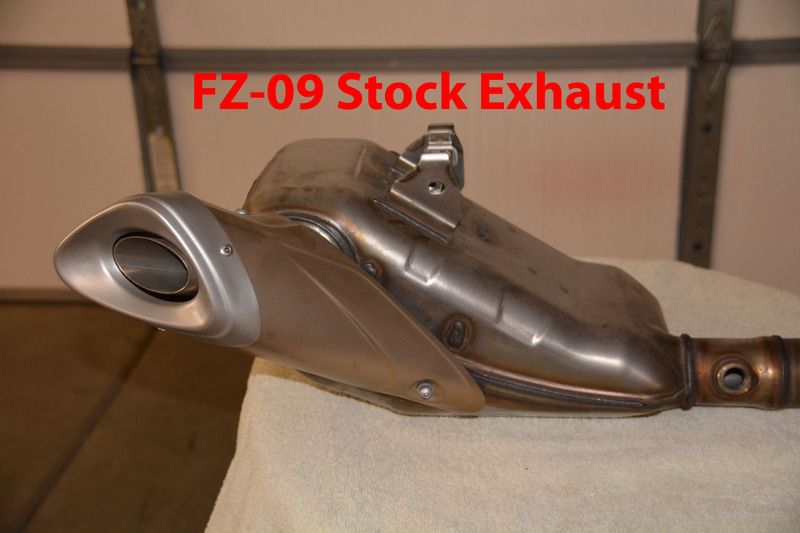
Yesterday I received my FZ-09 exhaust, purchased as a new take-off from eBay. I wanted to experiment on a spare exhaust, just in case this all goes horribly wrong, or I just get tired of being noisy and want to go back to stock.
First thing, I weighed it on my super-accurate scientifically calibrated bathroom scale: 17.5lbs
Then I started comparing it with the stock FJ-09 exhaust, looking for any differences.
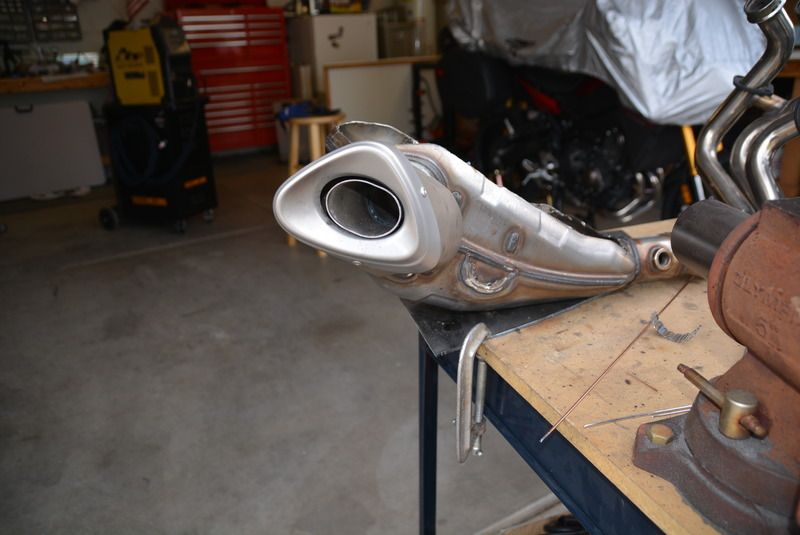
The first thing to note is that the cosmetic outlet cover is longer on the FZ version, and has an additional bracket forward. This would interfere with the centerstand on the FJ.
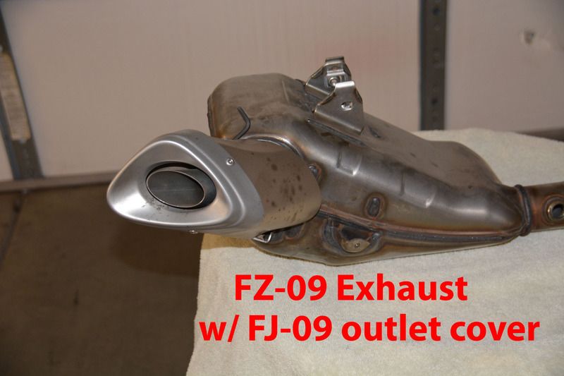
However, the FJ cosmetic cover fits on the FZ version, with one bracket being slightly in the way.
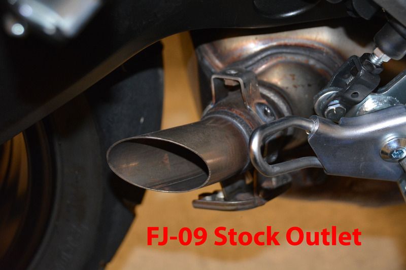
Here is the stock FJ with the cover removed showing the two brackets that hold the cover.
And here are the different brackets on the FZ version that will need to be removed.
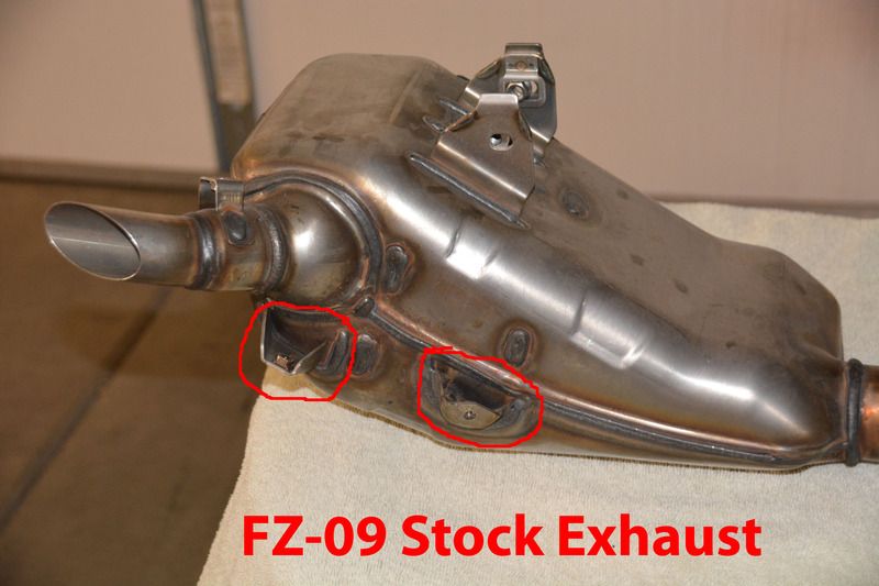
The exhaust itself, and the top bracket which mounts to the frame, appear identical.
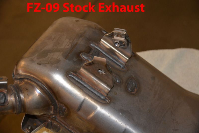
So, it appears that the FZ version can easily be used on the FJ by cutting off the two unused brackets, and fabricating a bracket for the FJ cosmetic cover, which is already required when increasing the size of the outlet tubing. Easy peasy! So, now we know we have a cheap source for stock exhausts!
Next step is to cut the muffler/cat section open and examine the guts. My intention is to do much more extensive surgery than the pioneers here, and perhaps construct a straight through exhaust, with no cat, similar to an aftermarket setup, but concealed in the stock box. Stay tuned....

Ty
-
Sounds fun! Please keep us updated, and pics please.
Ty
-
C25 is 75% Argon, 25% CO2 is standard mig welding gas here. .030" wire. TRI-MIX - 90% Helium - 7.5% Argon - 2.5% Co2 is the best for stainless, but I dont have another cylinder. These aren't structural welds, so strength is not an issue. Stainless flux core wire might be an option, never tried it.LOL....when am going to try this mod on my bike? When I get it! I seriously have to sell my Ducati 748R to @eatpasta when he bothers to come to Oz to pick it up!
The good lady of the house won't let me have 4 bikes....
So Ty, you didn't use gas with the Mig? C25, is this stainless fluxed core wire? I think the naming is different here. What gauge wire did you use? 0.9mm?
Do you recall your settings?
Thanks go to you 3 pioneers of pipeworx!
Cheers,
Steve
Ty
-
The mig tip is hard to get in around the pipe section. But look at the pipe next to it, only welded top and bottom. I'ts not structural, it's not going anywhere. Make sure you wirebrush the soot off the chamber wall before welding.
The muffler is stainless steel, so stainless wire is a must. Ty said he learned some things with mine concerning welding and mine came out nice. The muffler material is thin, so burn through is a possibility. Maybe Ty can post up his settings on his Mig to make things easier for you. So when are you going to work on your muffler? It ends up sounding very nice, and if you want it louder, just do the 2 inch exit pipe-ectomy later. I am happy with the way mine came out and is way easier to fabricate. The next time Ty and I ride together, we will compare sounds.Lovely Ty! right, got it now with removing the inside pipe. The Dremel tool will come in handy to do the inside part. Perfect, I have that covered!
I noticed only 4 small bead welds to secure the remnant S pipe to the cat chamber? Not all around?
If that's the case, even easier! The hardest part is to cleanly re weld the cover!
Is the muffler Stainless steel? Damn, will have to get stainless wire for the Mig.....
Thanks again Ty & Ulewz!
Cheers,
Steve
Yes, I used stainless wire. I dont have tri-mix gas, just using C25 which probably makes welding on this more difficult than it should be. But look at the funky factory welds on your muffler. Blackish fat, droopy beads. Probably quick hot fast welds, so as not to burn thru this material. I'd just burn a hole if I tried that. Probably robot welded.
Good luck,
Ty
-
Ok, so here's what I did to Lewis's muffler:
After cutting out the s pipe and drilling additional hole, you are still left with this remnant. This goes thru the outer shell and is welded to the outer tailpipe sleeve a couple inches from the tip. We want to remove that.

I used a dremel with a cutoff wheel to cut thru the inner layer only, going in from the outside tailpipe tip.

S pipe remnant removed.

Now the exhaust flow can go directly out the rear chamber relatively unobstructed.

Secondary hole getting pipe welded in.

Top welded back on. I had cut along existing weld line where possible this time. Helped when rewelding it back together.

To sum up:

Ty
-
Glad you like it Lewis!
Looking forward to hearing your review when you get a chance to give it a good riding test. Sounded great in your yard. A bit quieter maybe, maybe not, but the same deep sound. I learned a few tricks this go around with the welding. I'm used to welding on thicker material, so this was a good learning experience for me.
I was able to totally remove the stub of the S pipe, right up to the final necked down weld on the stock tip, ( papac200 will know what i'm talking about ) using a dremel from inside the exhaust tip end. So the rear chamber is totally open into the the tailpipe.
I did take some pics, and I will post them up when I get a chance.
And thank you for the expert mounting and balancing of my Suzuki's new rear tire!
Ty
-
Add some cheese?
Hmmm? What was that sorry?Sorry, did you say something? I can't hear very well, I recently developed tinnitus...

Ty


What did you do to your FJ-tracer-gt today?
in FJ-09 Tracer 900 General Discussions
Posted
Ty